 |
| June 27, 2017 | Volume 13 Issue 24 |
Designfax weekly eMagazine

Archives
Partners
Manufacturing Center
Product Spotlight
Modern Applications News
Metalworking Ideas For
Today's Job Shops
Tooling and Production
Strategies for large
metalworking plants
Wheels:
Revving up electrohydraulic power steering with virtual prototyping
FZB Technology uses multiphysics simulation to guide design improvements for electrohydraulic power steering systems.
By Lexi Carver
If you've ever driven a car with no power steering, you'll recall having to pull very hard on the steering wheel to turn the tires to match your movements. Thankfully, those days are past us. Power steering systems -- which make driving much more comfortable by providing assistance through steering gears -- have gone through many iterations over the years and continue to evolve with improved designs.
Until the 1990s, hydraulic and electric versions were most common. But these were the forerunners to the birth of a more fuel-efficient method called electrohydraulic power steering (EHPS). EHPS builds on the conventional hydraulic setup, but relies on an electric motor to power a hydraulic pump, rather than power from the car's engine (Figure 1). Since the motor output is adjusted according to steering wheel angle and vehicle speed, much less power is wasted.
The pump sends fluid from a reservoir to steering gears, which apply extra torque to turn the tires when the driver turns the steering wheel. The system also includes an electronic control unit (ECU), torque sensor, valve to control fluid pressure, and a pipe system.
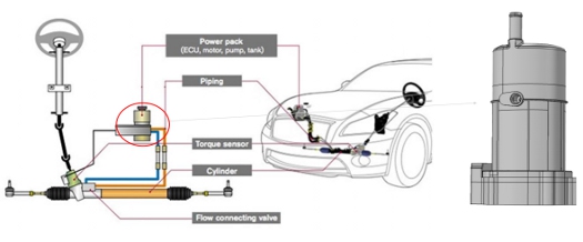
FIGURE 1. Schematic of electrohydraulic power steering (EHPS) system.
The Intricacies of EHPS
Designing a system with so many interrelated components is no small task, as the response of one part frequently depends on another. Seemingly minor adjustments can greatly affect successful function, efficiency, and reliability.
"One tool that expedites the design refinement process is multiphysics simulation," explains Feng Qi, senior mechanical engineer at FZB Technology in Plymouth, MI. FZB offers R&D for the automotive market, including the development of motors, sensors, keyless RFID ignition systems, as well as EHPS.
Engineers at FZB frequently use CAD and the COMSOL Multiphysics® software to model components of their EHPS designs (Figure 2). This helps them understand the behavior of the inner workings of the system, and move as close as possible to a final design before shifting from virtual prototyping to physical testing.
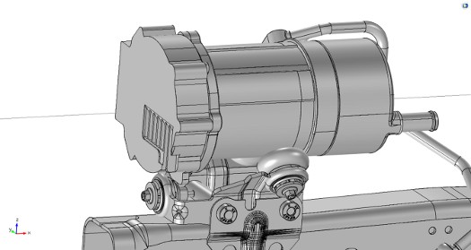
FIGURE 2. Geometry used for multiphysics analysis of the EHPS design. This design includes fins to support heat transfer to the surrounding air, mounting components, and fluid ports.
"Simulation helps us clearly understand a problem so that we can meet automotive requirements before building a physical model," Qi remarks. "We need to know how the system will perform at many levels: mechanical, thermal, fluid, acoustic, and electromagnetic."
He explains that validation and physical testing are expensive and time consuming, taking up to six months -- but even after testing, a successful prototype will still need further optimization. "That would be too slow for the design cycle, so we use simulation to speed up the process. We regularly talk with the engineers, for example, at Chrysler to improve our design in COMSOL software before any physical validation. Otherwise, we wouldn't be able to meet the requirements."
Seeking insight into the behavior under the hood, Qi's team at FZB modeled the major components of their latest EHPS design: the ECU, isolated mounting bracket, permanent magnet based motor, fluid reservoir, and helical gear pump. They performed simulations on each part separately, but also ran multiphysics analyses on the entire complex assembly, which differ in design for each vehicle model.
These analyses of thermal, mechanical, fluid, and electromagnetic phenomena helped the team to more quickly solve problems surrounding thermal performance, dynamic motion control, fluid delivery in the pump, and noise, vibration, and harshness (NVH) (Figure 3).
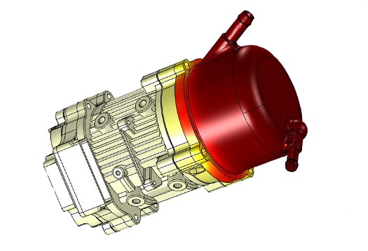
FIGURE 3. Steady-state and transient simulations were performed to obtain the temperature distribution in different parts when the pump is tested under various vehicle loads. The simulation results suggested ideal ranges for the local geometry, motor design parameters, size and number of vias on the ECU, and other thermally conducting features.
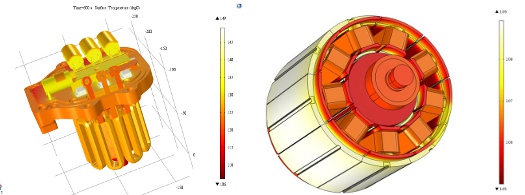
FIGURE 4. Temperature throughout the ECU and rotor assembly (left), and stator and rotor assembly (right). The model predicts system thermal performance when the product is installed on the vehicle.
Heat Under the Hood
One major factor in system performance is the ability to operate in a safe temperature range. Qi created a model that accounted for heat transfer in the pump and heat generation in the fluid that lubricates the steering gears. Using the fluid temperature as a variable boundary condition, his team was able to predict temperature distribution throughout the system for different operating scenarios.
Qi explains that the pump is under the most strain when a car's wheels are locked against a curb while a driver tries to turn them. When this happens in real life, the car's battery will still send power to the pump even though the wheels are stuck, generating heat in the ECU and motor magnet.
Based on operating conditions supplied by car manufacturers, his team was able to model how the power steering fluid would behave in this scenario. They also studied how the ECU components, such as MOSFETs and the wiring harness, would respond to temperature levels from the heat generation occurring when the car's wheels are locked. They used a multiscale modeling method, beginning with individual component simulations that they integrated to the system level, and correlated the results to physical test data. With this analysis, they were able to tweak boundary conditions and material properties to understand various configurations.
Temperature distribution also affects structural components such as the housing, stator, rotor, and rods in the motor (Figure 4). Thermal expansion of the metal affects the motor's efficiency, requiring more torque and RPM to deliver a desired power output to the pump. Fluid properties such as dynamic viscosity and density also change with temperature, requiring the gears to be adjusted in order to maintain smooth, consistent handling.
"This is the most challenging situation, when the vehicle is not moving and the pump has to do a lot of extra work," Qi says. "We want to stay in the temperature range where parts won't fail, so we modeled the setup for extreme situations to make sure it would hold up and perform just as well."
Qi modeled changes in the wall thicknesses of the motor, stator, and pump due to the thermal expansion and to see whether stress levels would surpass the yield stress of any part (Figure 5). The motor's stator presented a unique challenge, where thermal expansion would cause it to fail. Because they deduced this early on from the COMSOL simulation results, the team added a groove that would allow it to change shape without causing trouble.
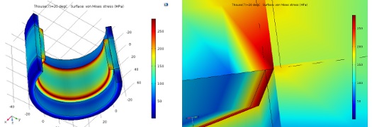
FIGURE 5. Stress levels in a simulation analyzing the interference fit of the housing and stator.
This geometry factor became critical for considering the interference fit and amount of the housing and stator. Because the housing and stator have different coefficients of thermal expansion (CTE), the interference amount and geometric thickness needed to be carefully selected to ensure that neither part would fail within the temperature range.
Fluid, Noise, and Electronics All Play a Role
The team also built an electromagnetic model to analyze the performance of the helical magnet and helical gear pump for different time steps during the pumping process (Figure 6). This gave them an understanding of how well the motor would perform over time, including an accurate estimate of heat loss on the coils and irons. This led to changes in the geometry that would accommodate a more uniform temperature distribution among components and parts.
They coupled the electromagnetic simulation to a CFD analysis to understand how it influenced fluid delivery and pump efficiency. They used PumpLinx® software, a program specifically designed for modeling pumps, to obtain fluid efficiency, flow rate, and pressure ripples.
Qi transferred the fluid data into his COMSOL Multiphysics® model, made geometry updates through SOLIDWORKS® software, and then created an acoustics simulation to study the vibrations (Figures 7 and 8). An additional rotordynamics simulation helped him identify critical speeds where the vibrations would increase dramatically, causing the gears to fail. This would generate abnormal noise, and decrease efficiency.
"Not only did we need to understand how loud the system would be, we also needed to know how it affected the electromagnetic and fluid behavior," Qi says. "They're all interconnected. We modeled a pressure ripple in the fluid, and in COMSOL analyzed how the ripple altered the airborne noise. From the results, we were able to optimize bearings, shafts, and the shape of the helical gears and fluid pressure release grooves in the helical gear pump bushing."
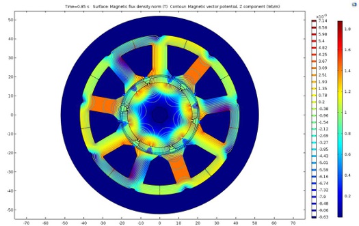
FIGURE 6. Simulation showing magnetic flux density and magnetic vector potential in a time-dependent study of the EHPS motor behavior.
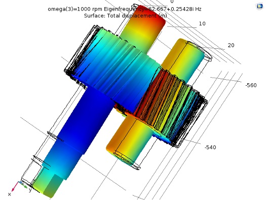
FIGURE 7. COMSOL results showing displacement of the helical gears for an RPM of 1000 and eigenfrequency of 2718.2 Hz, following the import of data from a fluid analysis in PumpLinx® software.
Paving the Way for Improved EHPS
Ultimately, the FZB team made significant design improvements to their pump geometry based on their COMSOL results. From the simulations they also generated a report on the power consumption limits in order to guide the design engineers in meeting automotive requirements. They studied how different boundary conditions affected energy consumption and power output from the pump, and checked the simulation results for different scenarios against data from real driving tests.
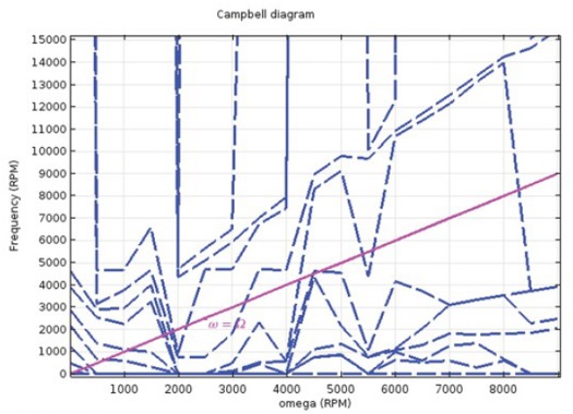
FIGURE 8: Campbell diagram generated in COMSOL showing the variation of eigenfrequencies with angular velocity for the helical gears.
"We chose COMSOL because we needed to analyze all the coupled physics behavior," Qi concludes. "Successfully carrying a vehicle from concept to market depends on many factors, and the timing of the design cycle can be very tight. We needed a truly multiphysics tool for this cross-disciplinary teamwork. COMSOL is very powerful for connecting many areas of physics with different boundary conditions that provide us with an accurate picture of how our EHPS design will perform."
REFERENCES
1. Qi, F., Dhar, S., Nichani, V., Srinivasan, C. et al., "A CFD study of an Electronic Hydraulic Power Steering Helical External Gear Pump: Model Development, Validation and Application," SAE Int. J. Passeng. Cars, Mech. Syst.
CONTRIBUTORS

Jinming (Jim) Yang, CEO, FZB

Zhonghui (Max) Bing, director, FZB

Steven Qi, manager, FZB

Liang (Leon) Yang, manager, FZB

Dahong Yu, executive director, Fuxin Dare Automotive Parts Co., Ltd., China

Ying Xie, manager, Fuxin Dare Automotive Parts Co., Ltd., China
NOTE: This article originally appeared in COMSOL News 2017 and is reposted here with full permissions from COMSOL. Read more in-depth simulation articles at www.comsol.com/offers/comsol-news-2017.
Published June 2017 Designfax
Rate this article
View our terms of use and privacy policy